After the 9/11 attacks, the detection of terrorist threats has been one of the top priorities of the US government. Oftentimes, terrorists plot to detonate explosives near important structures such as airports, military bases, or subways. While some terrorists have access to military-grade explosives, many rely on cobbled-together explosive devices based off of cheap nitrates, dubbed “Improvised Explosive Devices” (IEDs). If the military is to stop terrorists using IEDs, they need a method of detecting these devices.
One of the characteristics of volatile explosive devices is that they give off trace amounts of particulate matter (~1part per billion). In particular, armed IEDs give off a class of chemicals called “paranitrophenols.” If these chemicals can be detected from the air, then it can be possible to identify those carrying IEDs. These terrorists can then be stopped, preventing damage to critical structures and saving lives.
In this project sponsored by Redstone Arsenal, I worked with another student to develop a portable system capable of detecting trace amounts of paranitrophenol activity. This system consisted of five parts: the detection sensor, the analog filter, the transmitter, the receiver, and the GUI client. The detection sensor consisted of an array of zinc-oxide nanowires grown on a platinum substrate. These wires grew upward from the substrate, like hair on the top of one’s head (unless said person is bald, then…like their eyebrow hair?). The upward facing nanowire structre had two advantages over horizontal nanowire structures explored by other researchers. First, growing the wires vertically increased the number of nanowires that could be fit on the substrate. This allowed for increased sensitivity and robustness, as if a few wires broke it wasn’t as big of a deal if there were more to begin with. Second, when grown vertically, the nanowires exhibited an optical response as well as an electrical response to incoming paranitrophenols. This allowed us to detect a specific class of paranitrophenols used in IEDs, instead of detecting every type of paranitrophenol in existence.
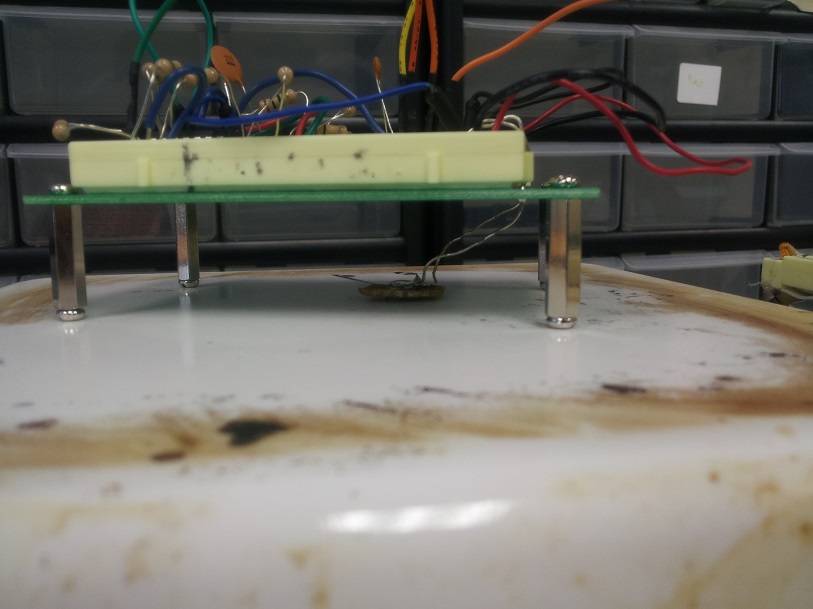
The analog filtering board (shown in its prototype state above) was responsible for regulating the power supplied to the sensor, as well as cleaning up and amplifying the signal provided to the transmitter board. The nanowire sensor was very fragile, and required a very precise voltage to be maintained across its terminals. In the presence of paranitrophenols, the device drew a few extra microamps of current, thus acting as a variable resistor. With the help of a transimpedance amp and a few other op-amps, the state of the sensor was correlated to a 0-3.3V analog signal output to the transmitter board.
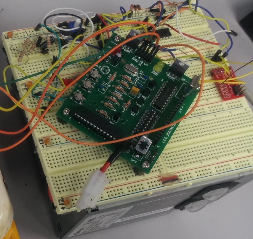
The transmitter board had three tasks. First, it contained a microcontroller which sampled the incoming signal from the sensor, and created a data packet to send to the receiver board. The microcontroller was capable of monitoring up to 6 analog inputs, and had a few other communication lines open to accommodate future sensor boards: SPI, UART, and 5 GPIO. Second, the transmitter board contained power regulation circuitry to regulate the battery power supply, providing the attached analog filtering boards with a clean 3.3V supply. Finally, the transmitter board contained a wireless transceiver module, which allowed the device to communicate with the transmitter board. The devices utilized the HopeRF module, which interfaced with the microcontroller over SPI and utilized the 433MHz band.
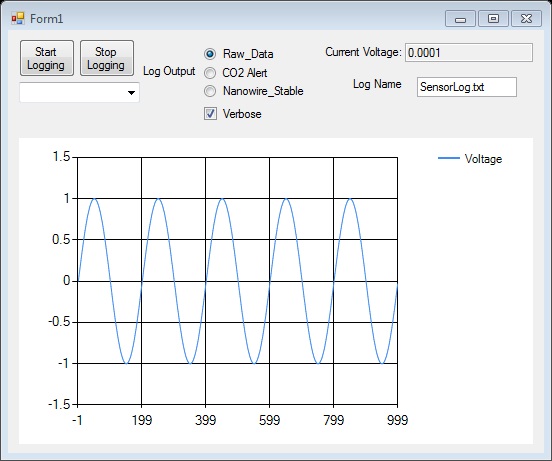
The receiver board had two tasks. First, it had a microcontroller and a HopeRF module, which allowed it to transmit and receive packets to the remote transmitter boards. The mesh networking scheme followed a star topology, with the receiver board in the center. Thus, multiple transmitter boards can be monitored from a single receiver board. Second, the receiver board maintained a USB connection to the client, allowing the user to monitor the status of the devices and send commands to the attached devices from a laptop. The GUI Client (shown above) logged the data and displayed it in a graphical format, allowing the user to actively monitor the status of the devices.
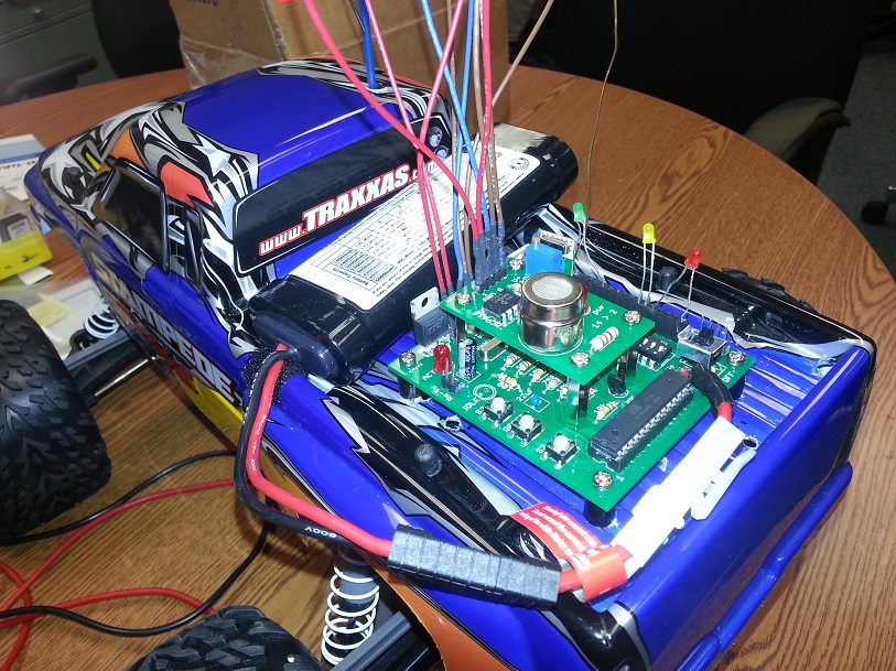
Here is the sensor mounted on our test device.
Completing this project involved a large amount of different skills: analog system design, digital system design, microcontroller programming and higher-level programming to name a few. The schematics for these devices are currently being used as references for future work at Redstone Arsenal.