Robotics is one of the most exciting fields, but also one of the most difficult to get started with. A robot has many moving parts, requiring knowledge in mechanical engineering, electrical engineering and computer science in order to create even the simplest robot. For a beginner, it can be overwhelming attempting to break into the field. Pre-built kits exist, but those usually fall into one of two categories: prohibitively expensive for those without governmental research grants or so underpowered and fragile they might as well be considered toys. In this project, I created a robust, scalable robotic platform that is robust enough to perform in a variety of outdoor environments. In addition, it must be affordable, costing less than $1000 to assemble from scratch. Also, it must contain enough processing power to allow for experimentation with autonomous navigation algorithms. Finally, it must be simple enough to assemble that one without a PhD in robotics could create the platform.
Fitting in with the “easy to build” requirement, a pre-made chassis is almost a necessity, as many do not have access to metal-working tools necessary to build a custom chassis. Fortunately, there are many different chassis options that are inexpensive, while remaining robust. After comparing the options, the Dagu Wild Thumper 6WD chassis was chosen. There are a lot of attractive features about this chassis. First, the chassis contains a differential suspension system, allowing the wheels to smoothly roll over rough terrain. In addition, the body is a brushed aluminum finish, which is light and strong. It is also very easy to assemble, practically coming pre-assembled out of the box. The one gripe I have with the system is the motors - they are of low quality and they are difficult to replace. However, for the price, this chassis can’t be beat.
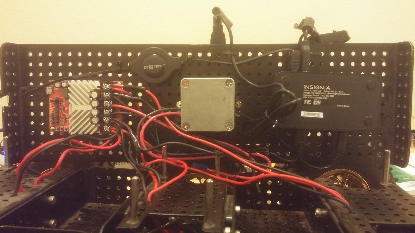
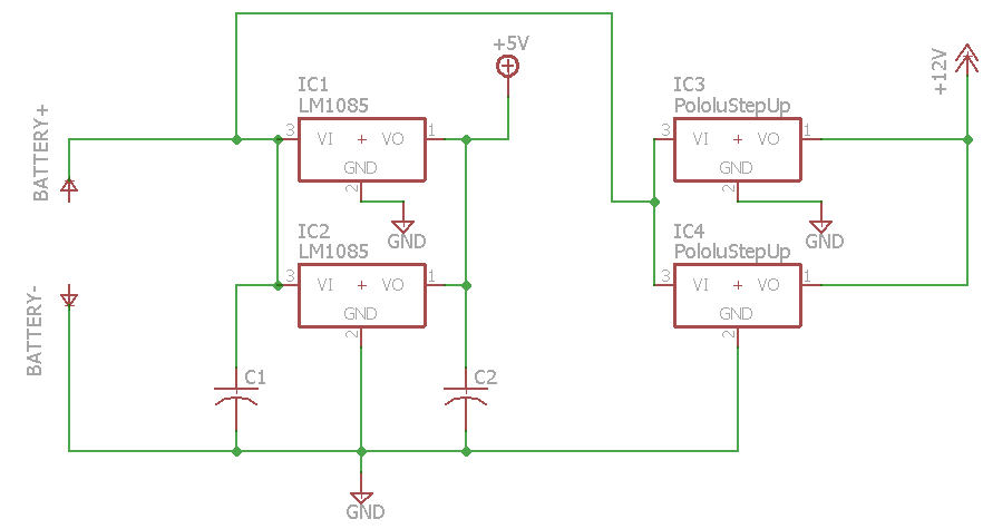
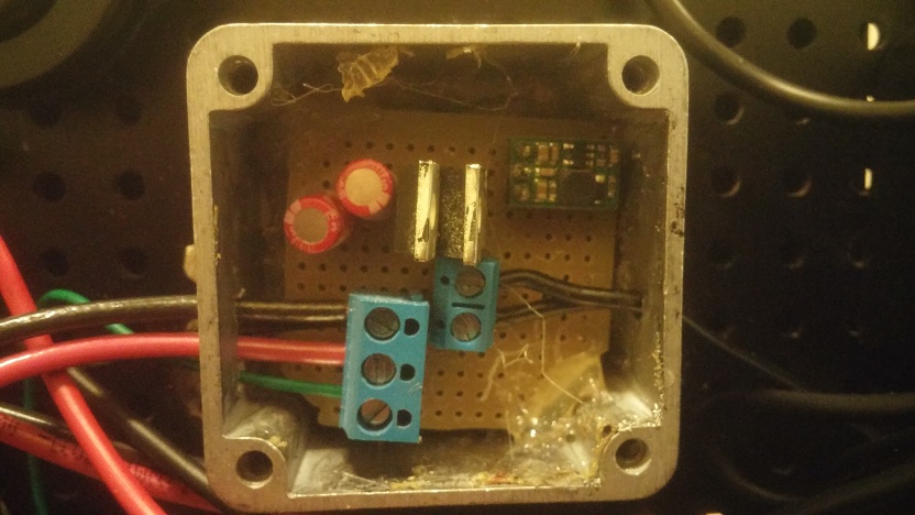
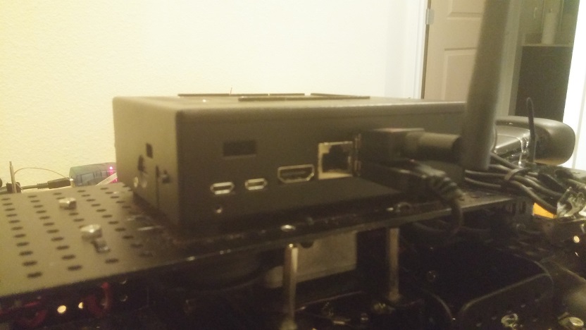
As this platform is intended for use with autonomous navigation experimentation, one of the major design goals is to leave as much room available for external sensors as possible. One of the innovative methods of accomplishing this task involves placing the drive train electronics on the underside of the chassis hood, mounting them upside-down. By doing this, the entire top of the robot is freed for the computational system and the supporting sensors. There are three major components mounted on the underside of the chassis hood. The most important system, and the only one that requires a custom circuit is the power distribution subsystem (encased in the silver metal box). The robot runs off of batteries, which supply a variable voltage proportional to the charge remaining. This does not bode well for the sensitive electronic components, which require a very precise input voltage to function.The schematic for the board is shown below, as well as its implementation on a segment of perfboard. It is a very simple regulator circuit, providing two voltage rails from the 7.2v input: a 5V rail capable of supplying ~6A used for powering the USB hub and a 12V rail capable of supplying ~2.8A used for powering the onboard Single Board Computer (SBC). Because the circuit is so simple, it is possible to put it together on perfboard instead of needing to get a custom PCB manufactured.It is also very small, fitting inside of the space requirements.
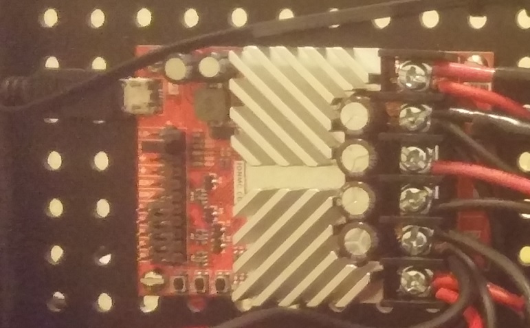
The next important electronic component is the motor controller, shown below. This electronic circuit is responsible for taking an input from the SBC and driving the motors. The motor controller needs to have two channels, as we need to be able to drive the left and right sides of the bot independently. In addition, it needs to be able to supply at least 15A of continuous current to each channel, as each motor can pull up to 5A when stalled. A few different motor controllers were used for prototyping, but eventually, the RoboClaw 2x15A motor controller proved to be the best option. Although more expensive than similar, PWM-based motor controllers, having a USB interface more than makes up for that due to the fact that fewer control wires will need to be run to the controller. In addition, it provides a plethora of functionality that is not available in the other controllers, such as battery level monitoring and encoder integration (note: this build does not contain encoders, but this is a benefit for other builds that may benefit from encoders). This motor controller connects over USB and emulates a Virtual Com Port (VCP), making it simple to use. It even comes with its own library, but for the sake of consistency, this build contains a custom class for interfacing with the controller (see the software section for more details).
The final piece of ancillary electronics stored under the chassis hood is a USB hub. As many peripherals contain a USB interface, most SBCs will quickly run out of USB ports. Thus, it becomes necessary to provide an expansion. There wasn’t much subtlety in choosing a part, as long as the hub is externally powered and reasonably sized, it would work for this purpose. An Insignia 7-port USB hub was used for this part, as it was readily available at the local Best Buy.
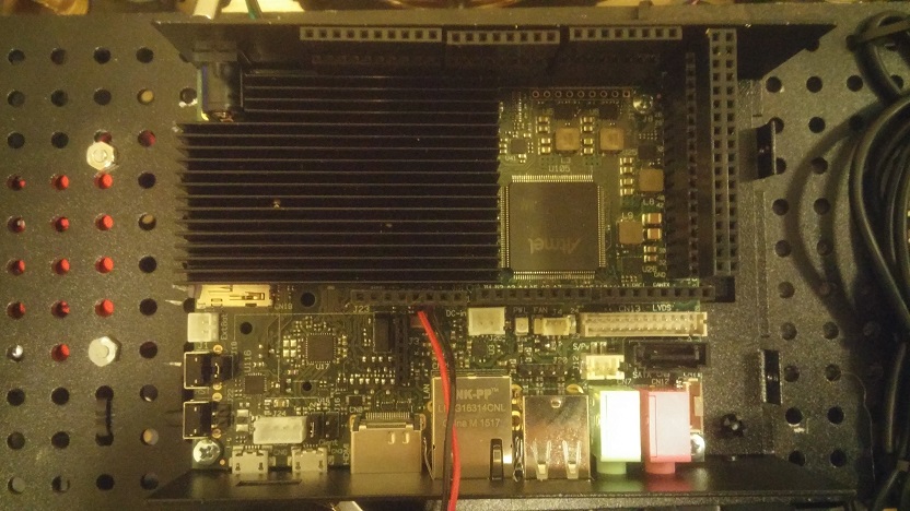
One of the most important decisions to make when designing a robot is which Single Board Computer (SBC) to use. There are a plethora of options, all which suit different niches. On one end of the spectrum, there are robots built out of boards based on the Atmel ATMega chipsets, running the Arduino bootloader. These chips are very simple to use, however lack the computational power to do anything reasonable. On the other end of the spectrum, there are Pico ITX form factor motherboards that contain full-blown x86 chipsets, but lack any sort of real-time control or low-level I/O interfaces such as ADCs and DACs. After experimenting with many different options, the board chosen for this build was the UDOO quad. This is a very new sbc, which contains a unique dual-chip architecture. The first processor is an Atmel SAM3X8E (referred to here as the SAM) microcontroller. This 32 bit microcontroller runs the arduino environment, making it easy to write code for. In addition, it offers a variety of interfaces, from GPIO and ADCs to CAN busses and USARTs, ensuring that we would be able to interface with any peripheral that we come across. While the SAM has a decent amount of processing power, it is still underpowered for all but the simplest robotic applications. In addition, it lacks an operating system, a prerequisite for most libraries used in robotics. To combat these weaknesses, the UDOO quad includes a quad-core Freescale I.MX6 processor (referred to here as the ARM) as the main computational engine for the device. This powerful chip runs a custom distribution of linux. Although not marketed as such, a robotics system is an ideal use case for this piece of hardware, as it requires both high computational horsepower and real-time control for peripheral interfaces. The two devices communicate over an integrated serial port, so interprocessor communication is simple. Even better, a robust case option exists to protect the board from the elements.
While the UDOO quad has some impressive specs, there are a few pain points associated with using the device. First, it is very picky about which version of the linux kernel you place on the device. Not all versions will allow you to flash the SAM from the command line, as the pins necessary for resetting the SAM are not exposed through the operating system. Ensure that you have flashed the UDOObuntu 12.04 OS to the card, not 14.04 or any of the other distros. You will know you have the correct version if the class /sys/class/gpio/gpio0 exists and can be exported.
Another pain point for the device is that the SAM and the ARM share the same pins for I/O. That is, both pins are connected to the same header, and thus each other. One needs to keep track of the pin states on both processors to avoid frying either of the chips (for example, by setting the SAM’s output high and the ARM’s output low). There are not pre-build libraries made for this, so this build opts to avoid changing any hardware from the Linux userspace, opting to perform all hardware manipulation on the SAM side. Oddly enough, the PWMs are also disabled be default for the ARM. One would need to recompile and reimage the kernel if one would want to utilize the PWM from linux userspace (unless one wants to depend on some sketchy DEVREGS calls).
The final major pain point when utilizing the UDOO is that the included wifi chipset is absolutely awful. After moving the UDOO 10 feet from a standard wifi router, heavy packet loss on the order of 50% was observed. This is a known issue with the board, and the solution provided by the UDOO devs is to solder an external antenna to the wifi chip. As there aren’t any well-exposed terminals for soldering antennas, this is a laughably bad solution. The easiest method is to buy an external USB wifi adapter and remove the onboard adapter. No additional USB bandwidth is used, as the on-board device communicates over the USB bus as well. Ensure that the device that you purchase utilizes the RaLink chipset, as there is no precompiled binary for the Realtek drivers (which compose a majority of cheap usb wifi adapters advertised to work with embedded linux boards). Worse still, attempting to recompile the kernel with the driver enabled causes kernel panics on startup. A confirmed working device can be found in the parts list for this project.
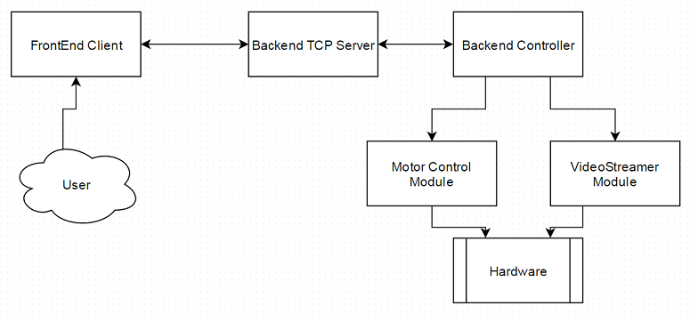
A high-level diagram for the architecture of the robot can be seen above. The user interacts with the robot via a “Frontend” client running on the host PC. This client is responsible for reading in the user’s input from a USB gamepad and relaying the commands to the robot via a TCP/IP link. In addition, the frontend displays data being streamed from the robot. The frontend is written in Java, prized for its ability to run across multiple platforms.
The backend consists of multiple different layers. The code is written in C++, balancing performance and modularity. The backend runs a TCP/IP server to which the frontend connects. Commands sent to the server are parsed and routed to the correct module. Presently, only a single module is implemented: the motor control module. When this module receives a command, it parses the values and sets the motors accordingly. This architecture is easily scalable to include many different devices; a module simply needs to be written dictating how to respond to commands sent from the frontend.
While most of the code is very straightforward and can be understood by the inline comments, one point deserves a bit more explanation: the hardware interface. Recall earlier that the SAM and the ARM share I/O connections. Because it would be nearly impossible to ensure that the pins would always be in a safe state, the design decision was made early on to do all I/O through the ARM. This required a robust method of communication between the ARM and the SAM. In order to accomplish this, an arduino program was written to accept command “packets” over the serial port, set the pins, and report the status regularly back to the ARM. The ARM then picks these packets up and routes them to the correct peripheral instance. In order to maintain consistence across threads, it became necessary to create a singleton “PeripheralManager” class that has a reference to all instantiated peripherals. In addition, there is a singleton “SerialPort” class that maintains thread-safe access to the serial port. When a peripheral is instantiated in user code (through a line such as “GpioPin p = new GpioPin(“GPIO23”);”) the peripheral first “registers” the instance with the peripheral manger. Then, whenever
a packet intended for the peripheral comes through the serial port, it is then routed to the device, which parses the state. Thus, multiple hardware entities can be instantiated and safely accessed in different threads.
Here’s a video of the robot in action!
The software source code can be downloaded from this github repo.