Introduction
In previous experiments, we build a robust, open-source robotic rover platform. With the creation of the UrdfSim robotic simulator, it would be a natural next step to use this platform to validate the performance of the simulator. Unfortunately, there are a few problems with this platform that make it problematic:
- The platform is physically small, which makes it difficult to mount sensors.
- There is little ground clearance, so the bot can easily run into problems when attempting to traverse standard obstacles in the ground.
- The platform does not have many USB / Ethernet ports, which makes it difficult to plug in multiple sensors. It will also be difficult to be able to plug it into the simulator and validate the system end-to-end, as there are no available ethernet ports.
- The motors on the bot are of low quality, which makes it difficult to drive the robot
- There are six motors on the bot, which makes the dynamics more complicated.
- The UDOO does not have an on-board GPU, which makes it difficult to run deep learning models in real time.
- The existing system is a monolithic C++ library, which means it would be difficult to integrate the connectors to the simulator.
- There is very little storage on the UDOO quad, which makes it difficult to store data.
- The UDOO software stack is a bit unstable, and does not have good customer support.
- The software stack contains a client desktop application, which adds additional maintenance burden for little value.
Given these issues, it seems instructive to redesign the robot to better suit this use case. The goal of this redesign is the following:
- Increase robustness, speed, and power of the bot to allow it to handle a much wider array of real-world terrain.
- Increase the reliability and ease of use of the bot.
- Design for the possibility of validation of the system inline with the simulator.
- Design to allow the system to run deep learning models.
Hardware Design
Motors
When choosing motors for a robot, there are a few important parameters of interest:
- Torque: This is a measure of how “strong” the motor is. You’ll need to be sure that the motor has enough torque to pull the weight of your bot when it’s going up a gradual slope.
- RPM: This is a measure of how fast the motor will spin.
- Current: This is a measure of how much current the motor will draw.
One subtlety is that these numbers change depending on the amount of load on the motors. Increasing the load will increase the current draw and torque output, and decrease the RPM. Generally, there are three points at which these numbers are important:
- No Load: This is when there is no load on the motor. By definition, the torque here is zero. This will represent the highest speed and the lowest current draw.
- Stall: This is the maximum amount of current and maximum amount of torque that the motor can provide. By definition, the RPM at this point is zero. Generally, the motors shouldn’t be run in this region often, but should design the electrical systems to handle this current draw.
- Peak Efficiency: This is when the motor is outputting the maximum power, and is the typical operating condition of the motor. Generally, the torque calculations should be based around these numbers.
Although these numbers give a general idea of the performance of the motor, it is best if one can find the motor curves. Here is an example of what a motor curve would look like, with the no-load, peak efficiency, and stall regions marked by red, green, and blue lines respectively.
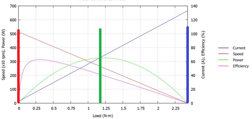
Here, we can see that the peak efficiency torque is 0.09 N-M, and the maximum current draw is ~60 A. Although that is a high stall current, it is less concerning in this design because it is unlikely that all four motors will be stalled at the same time. In addition, many motor controllers allow for current limiting, which can help mitigate this risk.
Generally, a DC motor used for a robotic drive system will have a very high RPM, and a very low torque. A gearbox should be used to transform some of the RPM into torque. Gearboxes will be specified with a ratio like “N:1”, which will reduce the RPM by a factor of N, and increase the torque by a factor of N. For example, a motor with an RPM of 10 and a torque of 10 N-M attached to a 2:1 gearbox will have an output RPM of 5 and an output torque of 20 N-M.
For this application, we selected the RS-775 motors from Banebots and used the 64:1 gearboxes. When mounted with generic 8-in diameter wheels, this gives our bot a max speed of 2.3 M/s, and a torque of 65 N-M, which should be more than sufficient to handle the loads that we would want to place on the bot.
Sensors
For this bot, we decided to include the following sensors:
- IMU: For the IMU, we used the MPU-9250. This would give acceleration, angular velocity, and magnetic field information. This sensor is a popular sensor, being used in many consumer electronics boards. In order to make the device easier to use, a sparkfun breakout board was ordered. This device connects to the outside world via SPI.
- GPS: In order to receive GPS information, the Adafruit Ultimate GPS sensor was integrated into the design. This sensor uses UART to communicate with the outside world.
- Xtion: The Asus Xtion sensor is an interesting image sensor. In addition to giving a RGB image, it gives out a depth image, which it estimates via an IR sensor. This device will be useful for obstacle detection.
- Bottom-Facing Webcam: One of the experiments that this platform will be used for will be visual odometry. For this, it is desired to have a downward-facing webcam which can be used for this purpose. For this, a standard off-the-shelf webcam is used.
- LIDAR: LIDAR sensors are popular in robotic applications for their ability to generate point clouds. The lidar integrated into this system is the same one used in the neeto vacuum cleaners, which has a 360 degree field of view, a 1 degree angular resolution, and a 6 M range.
The Xtion, webcam, and LIDAR all connect via USB, while the GPS and IMU are using lower level protocols (SPI and UART). The computing board will most likely be running a higher-level operating system, which will make it difficult to use SPI and UART. To solve this, the IMU and GPS are attached to an arduino, which will then communicate with the control board via USB. These will all be connected to powered USB hub, which will then be connected to the control board.
Motor Controllers
When considering motor controllers, there are a few important points to consider:
- Communication Protocol. Most inexpensive motor controllers communicate with the outside world via PWM. This is a bit difficult to use from a board running an OS, so a motor controller with USB device is preferred.
- Current Output. Current is specified with two numbers - peak and continuous. Peak current is the absolute maximum that the motor controller can provide without shorting. This is generally only available for a short period of time, however. Continuous current is the maximum amount of current that can safely be provided for a long period of time to a motor.
After considering a few options, this design settled on the Roboclaw motor controllers for a few reasons:
- USB communication.
- 60A peak current, meaning that a stalled motor won’t destroy the motor controller.
- A current limiting feature. Although not foolproof, it adds an additional layer of robustness to the electrical system.
- A custom-designed case with a fan, which will allow the motor to automatically cool itself.
Single Board Computer
One of the requirements for the onboard computation is the ability to run deep learning models. For this, we selected the Jetson TX2 board, which contains an on-board GPU. This allows libraries like tensorflow to be used to run deep learning models in real time. In addition, the board runs a full ubuntu OS. This means that code that is developed on an external computer (like a laptop) will be able to be run on the Jetson with little changes. Finally, the board contains a bunch of different connectors, which makes it convenient with which to develop and interface.
Wireless Router
Although the robot will generally be autonomous, the user will need to be able to communicate with it wirelessly. Although we could use the wifi abilities of the Jetson, a wireless router was included in the design in order to decrease the amount of work the control board needed to do. We chose the mango router for a few reasons
- Wired connector. More robust than wireless. Also makes developing in the lab more convenient - the jetson can connect to the internet over the lab wifi and the user can SSH via the ethernet connector. This makes it easier to download and install packages onto the jetson.
- Small size. The device is only 2.5” x 2.5”.
- Inexpensive. The device was $20 on Amazon.
Chassis and wiring
After the above components were selected, the chassis needed designed. There are a lot of different chassis material options for building a robot. For this application, acrylic was selected for a few reasons. First, with acrylic, the displays for any on-board sensors can be read through the chassis body, allowing for easy debugging of the bot. This also makes it easier to plug in connectors, as it’s possible to see the connection through the base of the bot. In addition, acrylic is waterproof, which allows it to handle light adverse conditions such as mist. Finally, acrylic can be laser-cut, which makes the manufacturing of the chassis easily reproducable.
To lay out the chassis, Visio was used. This allowed each of the components to be measured and placed before the the acrylic was cut. Once cut, the components could be attached with standard nuts and bolts. Also, the outline and name of each of the devices could be rastered into the acrylic, making assembly even easier. The picture below shows what the cut acrylic looks like.
After the acrylic was cut, the parts were wired up. A resettable fuse was wired in-line with the motors to serve as a kill switch. The bot is powered by 2x 24v, 5 AH batteries, which gives the bot plenty of runtime before needing to be recharged. Initially, a custom PCB was used to regulate the control electronics, but this was abandoned for a set of off-the-shelf switching regulators.
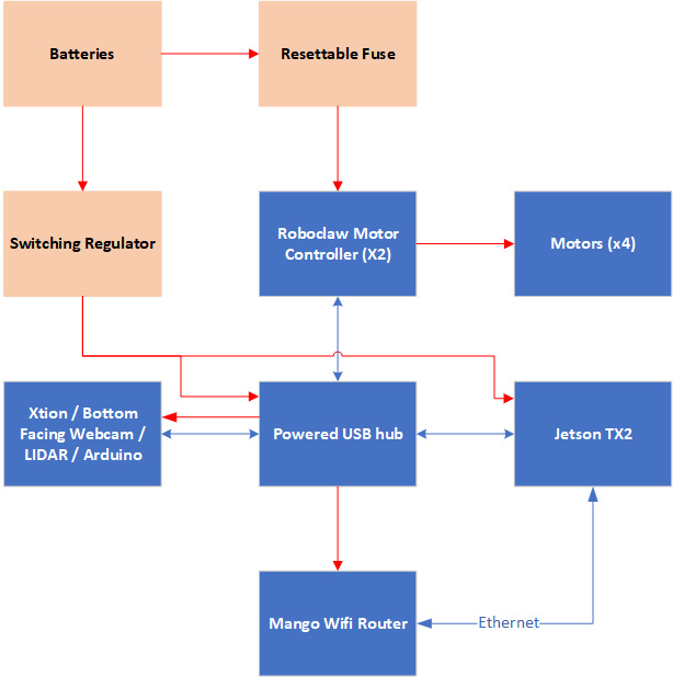
The diagram below shows the final hardware architecture. In this diagram, blue rectangles represent digital electronics, while tan boxes represent power electronics. The red arrows show the flow of power to each of the components, while the blue arrows show the communication lines between the components. Unless otherwise noted, all modules communicate via USB.
Software Architecture
To ROS or not to ROS
In the previous iteration of the software, the decision was made to write the software from the ground-up. While this was an interesting exersize, this led to a lot of boilerplate code. In addition, it would be more difficult to integrate the code with the simulator to test inline. To this end, the decision was made to use ROS. The architecture of the final ROS solution can be seen in the figure below. In this diagram, the ovals represent hardware devices and the rectangles represent ROS nodes. Red lines represent custom communication mechanisms (e.g. using a C API to interact with the hardware), and blue lines represent ROS topics.
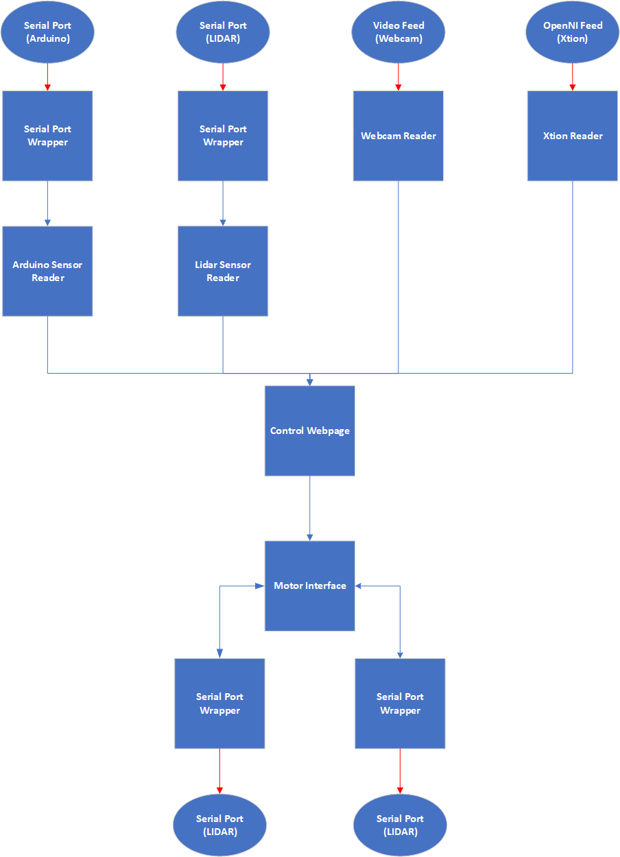
At the start, there are nodes that own each of the sensors. These nodes continuously poll the sensors and publish the data to topics. The data placed on these topics are then processed by additional nodes before feeding the output into the node that communicates with the motors. To integrate with the simulators, only the nodes in the first and last layers need to be substituted with a simulator integration node.
Control Webpage
In the previous iteration, a separate client application was developed in order to communicate with the robot. While effective, this introduced a lot of problems:
- A lot of boilerplate code was needed to be written in order to allow for the state of the bot to be communicated to the client and displayed.
- Generally, the client library is written in a different language, and has a separate build process from the bot.
- It is tricky to design a cross-platform application. Newer frameworks make it easier, but there are still plenty of edge cases that need to be considered.
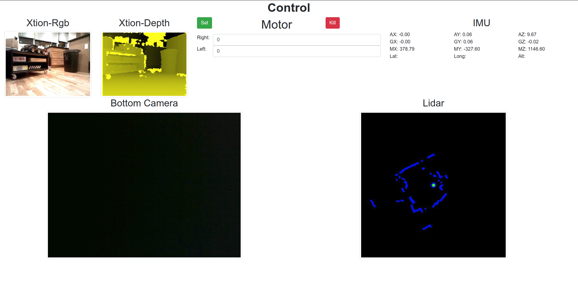
In order to bypass the need to maintain an additional console application, an additional node was developed that serves a simple webpage via flask. Clients would then connect to the webpage and be able to view the status of the sensors, as well as control the motors. This gives a quick, cross-platform mechanism for checking on the health of the robot. In addition, the user can drive the robot with a gamepad. A screenshot of the control webpage is shown below.
Lessons Learned
While the fabrication process was relatively straightforward, there were a few roadbumps hit during the fabrication process. While not fatal, these design problems can cause frustration during the build process, and can lead to ruined parts. Here are some of the non-obvious issues that were discovered while building the bot, which should be considered if the bot were to go though another design iteration:
- Leave space for hands and wires when designing the electronics box. While it is desirable to have a small footprint, be sure to leave enough space to be able to easily reach all of the electronics and plug/unplug all of the cables. The wires take up a surprisingly large amount of space! In this design, it can be tricky to plug or unplug the USB cables due to lack of hand space.
- When laser cutting, start with wood. It’s quicker to cut, and much less expensive. Once the design is finalized, then a cut with acrylic can be done.
- Do not attempt to glue laser-cut acrylic. The high heat changes the chemical composition of the acrylic, which means that the glue won’t hold. For this build, I went to Home Depot and got some L brackets, and used those to hold the box together.
- Use silicone-based wire rather than PVC-based wire. It’s much easier to bend, and not much more expensive.
- Do not use a vice to press gears onto motor shafts. With most motors, a pinion gear will need to be pressed onto the motor shaft before being used with a gearbox; the banebots motors are no exception. Initially, a vice was used to press the gears on. While it appeared to work, it turns out that this will usually bend the shaft slightly, which will then cause the gearbox to seize up when under load. The correct way to press on the gear is with an arbor press, which will prevent the motor shaft from bending.
- While a USB hub may support many connections, it may not be able to power all of them. One of the problems discovered close to the end of the design is that the sensors were randomly disappearing. They’d be working fine, and then the /dev node would disappear. Ultimately, this turned out to be a defect in the USB hub that was used - while it had enough connectors for 8 USB plugs, it could only provide power to 5 at a time. To solve this, we installed a second hub and connected it to the first. This allowed all of the devices to receive power.
- Have a wired power supply for the bot. 24V supplies can be found on Amazon cheaply; it will save a lot of time as opposed to having to charge and re-charge the batteries.
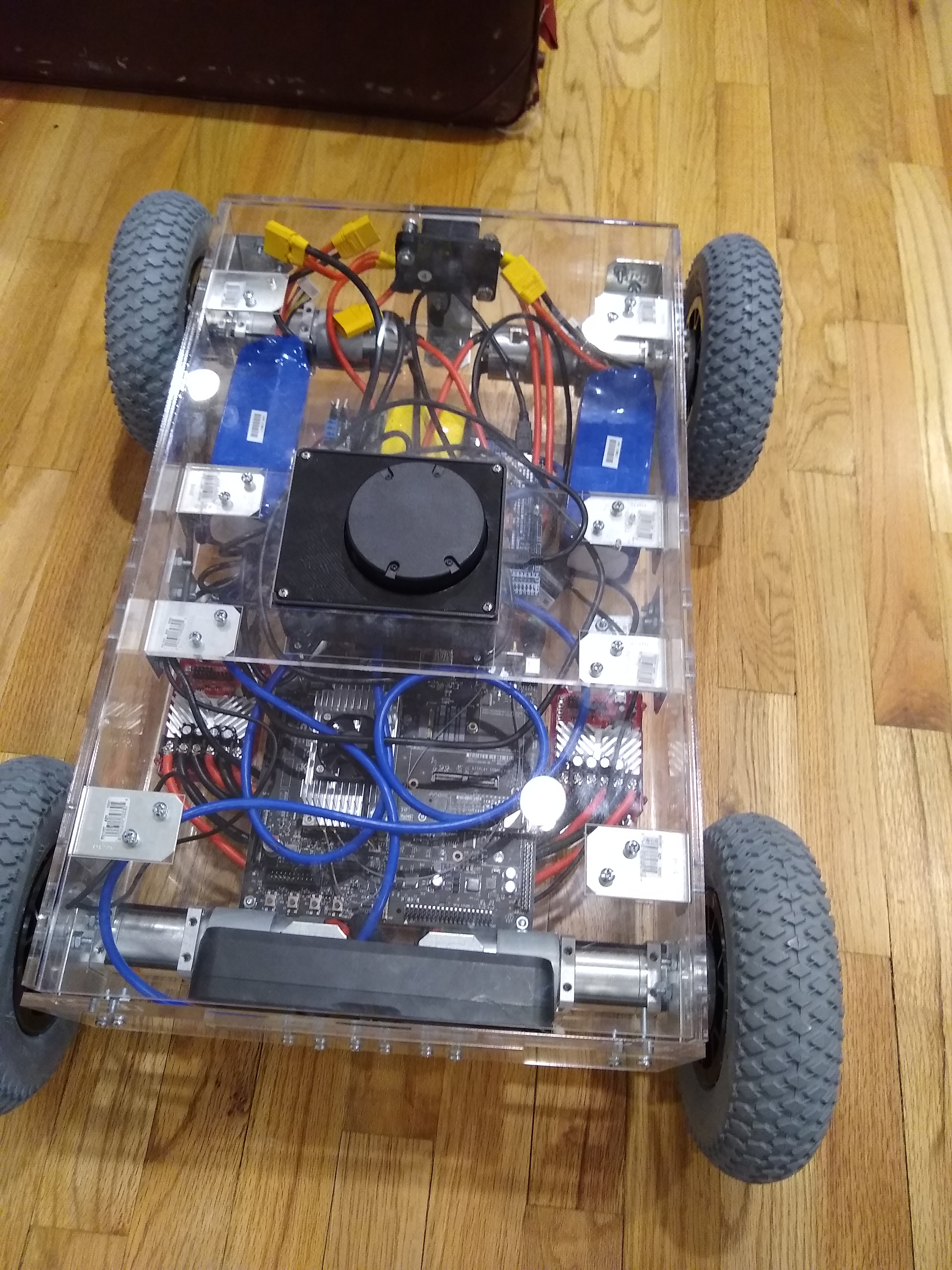
Here is a shot of the bot in all it’s glory, ready to roll!
Summary
In this post, we improved on the design of the open-source platform for robotic experimentation. The new design supports many more sensors, a much more robust mechanical system, and the ability to run embedded deep learning models. In addition, it is designed for use with the UrdfSim simulator, which will allow it to be used to validate the performance of the simulator for Sim2Real applications. The designs and associated code for this bot have been open-sourced, and can be found at this github link.